Lavoisier's Oil Analysis
"Traité Élémentaire de Chimie" (1789) vol. II, chap.VII, p. 493-501
For over 150 years, from the time of Lavoisier (1780s) until World War II, combustion analysis was the primary tool for figuring out what one was dealing with in organic chemistry. Much of our current knowledge was developed using this tool. The principle improvements over this long period involved increasing convenience and reducing the sample size necessary for accurate analysis. Lavoisier's analyses could consume more than 50 grams of organic oils and required a team of operators and expensive apparatus. Forty years later Liebig's modification of Berzelius's approach required only 1% as much sample as Lavoisier's (0.5 gram) and could be performed quickly by a single student with cheap equipment. Nearly 100 years after Liebig Fritz Pregl received the 1923 Nobel Prize for miniaturizing the scheme to use only 1% as much sample as Liebig (5 mg or less).
Combustion analysis is still considered a necessity for characterizing new compounds, although much of the motiviation for this 'necessity' is traditional, since analysis by spectroscopy is typically easier, more informative, more sensitive, and certainly less destructive. A typical current analyst requires a minimum of 2 mg for Carbon/Hydrogen/Nitrogen analysis, reports typical errors of 0.45% or less, and charges about $35.
Development of reliable, convenient elemental analysis by combustion was the reason organic chemistry "took off" during the first half of the 19th Century. Liebig's combustion apparatus was a key development and was universally copied, even by those who disagreed with him. Below are shown examples from Lavoisier (1789), Prout (1827), Liebig (1831), and Dumas (1841).
"Traité Élémentaire de Chimie" (1789) vol. II, chap.VII, p. 493-501
|
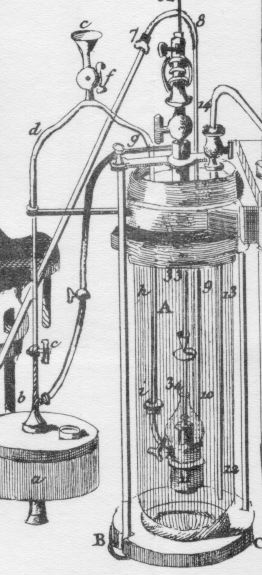
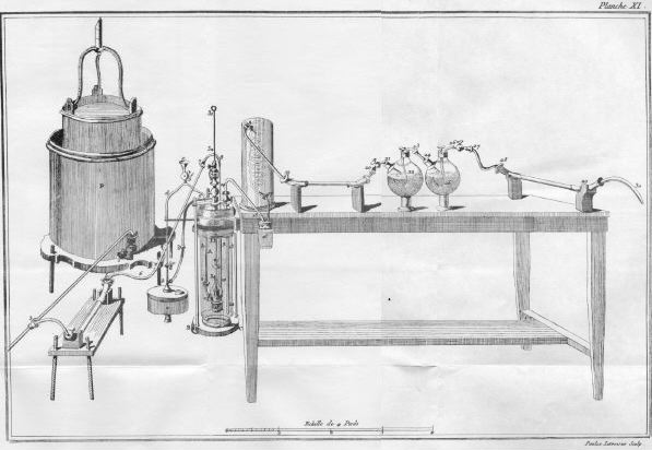
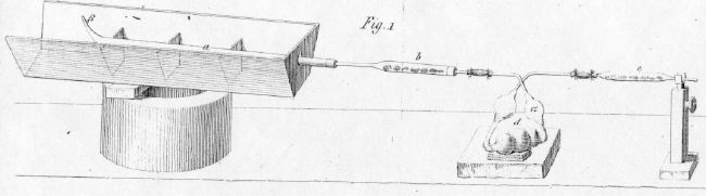
In this apparatus air from the large "gasometer" (P) at the left is fed through a drying tube (on the bench) and tubes 6-7-8-9-10 (see detail at the right) to allow combustion in the lamp inside vase A. The oil to be analyzed is siphoned from reservoir a through tubes d-g-h-i. The products, steam and CO2, emerge through 12-13-14. Water condenses and collects in the jar near the left table leg. Moisture that is not condensed in the coil above the jar is absorbed in the following horizontal drying tube. CO2 is then absorbed by potassium hydroxide solution in the two flasks (22 and 25 below; Note the hooks that allow stirring to facilitate gas absorption). Any moisture lost from the flasks is absorbed in the final horizontal drying tube. Measuring the increase in weight of the jar, flasks, and drying tubes allowed determination of the amount of water and CO2 formed and thus of the amount of hydrogen and carbon, respectively. 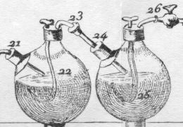 |
|
|
|
This was combustion analysis on a grand and expensive scale. According to the scale of feet on the bottom of the plate, the table was about 8 feet long. It must have required a team of operators to feed the air, feed the oil, attend the wick of the lamp, and stir the CO2 flasks. Contemporary drawings show three or four experimenters operating a simpler respiration apparatus, while Mme. Lavoisier keeps records on the side. The reservoir could obviously contain hundred of milliliters of oil, and a second gasometer, offstage to the left, could alternate with the one shown to supply an unlimited amount of air. It is not obvious (at least to me) that Lavoisier ever actually constructed and used this elaborate device. This may be a foreshadowing of plans for the Superconducting Supercollider. Lavoisier's organic combustion analyses of 1784 and 1788 used a simpler apparatus to burn up to 60 grams of sample. |
||
|
Note, in the lower right corner, that the plate was etched ("Sculpsit") by Mme. Lavoisier. |
|
|
Philosophical Transactions of the Royal Society of London, 1827, 117, 355-388
|
The London physician, William Prout, recognizing that "Organic chemistry is confessedly one of the most difficult departments of the science", took great pains to make the most accurate combustion analyses possible. Like Lavoisier, he had other responsibilities and did most of his scientific research and writing before a 7 AM breakfast. |
||
|
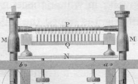
In 1827 Prout described the elaborate apparatus at the right to determine the ratio of hydrogen to oxygen in organic compounds. The sample to be analyzed (containing C,H,O) was mixed with CuO and placed in a glass tube (P, in the detail below) between two U-tubes containing pure oxygen gas over mercury. The multiple-flame alcohol lamp, Q, was then used to heat the tube until the CuO oxidized the sample. Meanwhile the product Cu2O was reoxidized to CuO by oxygen gas passed back and forth over the sample by draining mercury from the stopcock at the bottom of one U-tube while adding mercury through the funnel of the other to move the mercury "pistons" up and down .
When the sample had cooled and the Cu2O had been oxidized back to CuO, the mercury columns, graduated in 1/100ths of a cubic inch, were used to measure the total change in gas volume. Conversion of carbon to CO2 would not change the gas volume (one molecule of O2 becoming one molecule of CO2). When the H/O ratio in the sample was greater than in water, conversion of hydrogen to water would reduce the amount of gaseous O2. When the H/O ratio in the sample was smaller than in water, there would be net evolution of O2. In a separate experiment without gaseous oxygen, in which CuO alone oxidizes the sample, the increase in gas volume (CO2) measured by the same apparatus shows the quantity of carbon in the sample. Sample sizes apparently were in the range 0.25-0.5 grams.
|
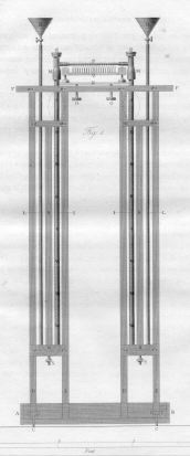
Click for an enlargement of the left manometer |
|
|
This apparatus was quite expensive and tedious, and it was impossible to measure the amount of product gas by volume as precisely as Liebig could measure it by weight in the procedure below. Still Prout was very accomplished and could measure components within 1-2% in favorable cases. His reputation for truly fabulous precision is undeserved. |
||
Combustion analysis was extremely tedious and demanding, leading Wöhler to write to Berzelius in 1828, "I recently performed a small experiment, appropriate to the limited time I have available, which I quickly completed and which, thank God, did not require a single analysis."
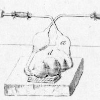
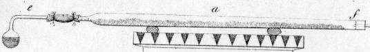
Justus Liebig (Annalen der Physik und Chemie, 1831, 21, 1-43) designed an apparatus that made combustion analysis routine. His diagram shows how the heating was done by placing coals in the trough surrounding the combustion tube a. Tube a contained only the substance to be burned and CuO, the oxidizing agent.
H2O was absorbed by CaCl2 in tube b, while CO2 was absorbed by concentrated caustic potash (KOH) in d. At the end of the experiment the pieces of the apparatus were separated and the gain in weight of b and d was determined.
This simplified apparatus was cheap, could be operated by a single student, and required only 0.5 grams of sample. The opportunity to learn to use this apparatus from the master was no doubt one of the main attractions that made Liebig's Giessen laboratory THE great teaching center for chemistry in the first half of the 19th Century.
|
|
The detail at right shows the 5-bulb apparatus (d) during combustion. CO2 is entering through bulb a and pushing the solution up into the 5th bulb. Notice the two pieces of wood that prop up the front of the apparatus making it tilt toward a. Why is this necessary? (What would happen if it tilted in the opposite direction?).
[The 5-bulb "Kaliapparat" became so important in chemistry that it is featured in many chemical heraldic devices, such as the logo of the American Chemical Society and the southwest corner of Sterling Chemistry Lab - look up to the left as you approach from Prospect Street. (click for more information)]
When combustion is complete and tube a begins to cool, the solution begins to rise into bulb a. (Think of two reasons why) At this point Liebig would snap off the tip of tube a (at b) allowing air to enter a. He would then suck gently on the far right end of the apparatus to pull air through the train bringing the remainder of the H2O and CO2 into b and d, respectively. He sucked with his mouth. Chemists were macho in these days before OSHA protection, and occasionally they paid the price.
Tube e at the end of the train contained caustic potash and was included only when the substance to be analyzed contained nitrogen. It served to trap moisture that a vigorous stream of N2 might otherwise carry out of d.
Note that the "combustion train" is held together with pieces of thin rubber tubing. Before adding coals to begin the combustion Liebig had to be sure there were no leaks. He would suck gently to raise the solution in one arm of the 5-bulb apparatus, then seal the tube and wait for 15 minutes to be sure that the solution did not fall again.
Nitrogen-containing samples were more troublesome, because the N2 product had to be measured by volume, not weight. Furthermore, there was typically relatively little nitrogen in the sample (compared to C and H), and one obviously could not suck air through the sample, since it would introduce N2 and O2 that could not be distinguished from the product. There was also a problem when oxides of nitrogen formed rather than N2 itself, though this could be eliminated by including finely divided copper metal in the combustion tube.
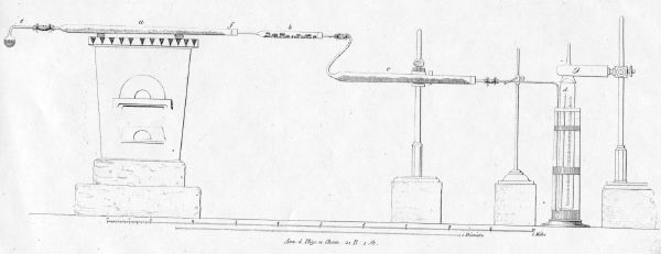
Here is the apparatus Liebig described for nitrogen determination in the same 1831 paper. He realised it wasn't so great, admitting "I only believe that among bad choices, it is the least bad." ("Ich glaube nur, dass sie unter den schlechten die am wenigsten schlechte ist.")
|
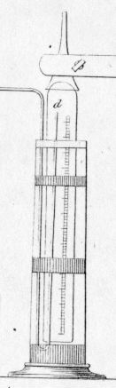
In this apparatus the CaCl2 in b absorbs the H2O, and the potash in c absorbs CO2, while the other gases (the original air and most of the N2) collected over mercury in cylinder d (shown on the right). Of course at the end of combustion some N2 remained in e-a-b-c, and some CO2 in e-a-b. The N2 was no problem, since it simply replaced air that was collected d and measured as N2, but CO2 had to be removed so that there would not appear to be too much new (nitrogen) gas. |
|
|
|
This was accomplished by tilting bulb e to pour its potash solution into a. After 2 hours all of the CO2 had been absorbed and one could measure a volume of gas equivalent to the evolved N2 in d.
|
||
|
Determination of nitrogen by volume was typically accurate only within 10%, while determination of carbon by weight of CO2 was accurate within 1-2%. |
||
This combustion train was used ten years later by Dumas and Stas (Annalen der Chemie und Pharmacie, 1841, 38, 141)
Notice the similarity to Liebig's design of a decade earlier, although there are a few refinements, such as 1 and 8 below.
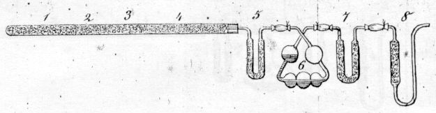
Apparatus for Organic Analysis
1. CuO and KClO3 : When heated this mixture generates O2 which carries the other gases through the apparatus. This obviates the necessity for breaking the tube at the end of the experiment.2. CuO
3. Substance mixed with CuO : When heated the CuO converts carbon in the substance to CO2; hydrogen to H2O; and nitrogen to N2. These gases are carried down the train to 5 by the stream of O2 from 1.
4. CuO
5. CaCl2 and H2SO4 : These substances absorb H2O
6. Liebig's 5-bulb apparatus : As the gas bubbles from bulb to bulb, CO2 is absorbed by a concentrated solution of caustic potash (KOH)
7. Potassium succinate and dry potash, K2O : Traps any H2O and CO2 that escape from 6.
8. Aspirator with caustic potash : Keeps atmospheric moisture and CO2 from entering traps 5-7.
At the end of the experiment the increase in weight of 5 measures the amount of H2O formed in the combustion and the increase in weight of 6+7 measures the amount of CO2.